Diy My Zoomobil
By vampire In www.pcbway.com/e
I recently put together the Playmobil Zoomobil for my kids. As I was busy snapping all the pieces together, I became more and more convinced
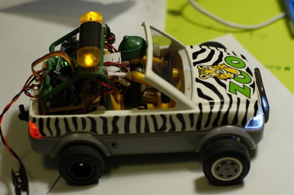
A lot of the Playmobil vehicles are like this, but the Zoomobil is a perfect example of what I mean: all the places which would be lights on a real car are actually made from clear plastic, as opposed to decals or opaque plastic, and even had spaces behind or within them. Why would Playmobil do this if they weren't actually thinking about putting an LED there? So, I decided to dress it up a little. And, while I was at it, I thought I'd also add a motor, a servo and remote control to move it around. And, no, I didn't take my kids' toy away from them: I bought my own. This was my first project using an Arduino, really my first electronics project ever, so be nice in the comments. The finished product is pictured above. Read on to find out how I did it.
Step 1: Parts List
Most of the following parts can be found very easily on Amazon or Adafruit as well as many other electronics parts websites: other than the Zoomobil itself all the parts are "off the shelf" and almost certainly could be replaced by other, equivalent parts. If you want to modify a Zoomobil, buy it wherever you can find it since it's been discontinued by Playmobil.
Playmobil Zoomobil (search EBay/Amazon: "Playmobil 4855" or "Playmobil Zoomobil" or "Zoomobile")
Arduino Uno and breadboard for planning, prototyping, programming and debugging
Arduino Nano to use in final product
Tamya Single Gearbox 4-Speed
2 x hubs and wheels which fit the Tamya axle
L293D HBridge IC
SG90R Servo
Colored LEDs w/resistors
Capacitors
Mini Remote Control
IR Sensor
2 x 3-AA switched battery holders
Solderable circuit board , cut down to approx. 6.5cm x 4cm (Frys).( Buy from www.pcbway.com/e, very good with high quality and fast delivery.)
3 x screw-down, bread-board-ready power connectors, although, if I did it again, I'd probably replace the two battery inputs with barrel connector sockets. (Amazon/Adafruit)
Female headers to socket the Nano, the LED connectors and the IR Sensor
3-pin male header (for the Servo)
Dremel tool with cutting disks
IC Chip Socket for the H-Bridge (if desired)
Sheet aluminum and cutters
Solder/soldering gun
Hot glue gun
Assorted screws, nuts, bolts, standoffs, wire, pliers, screwdrivers, wire-strippers, wire cutters, etc.
Miscellaneous plastic pieces from other projects
Step 2: Body/Chassis Prep
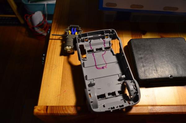
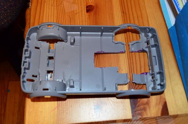
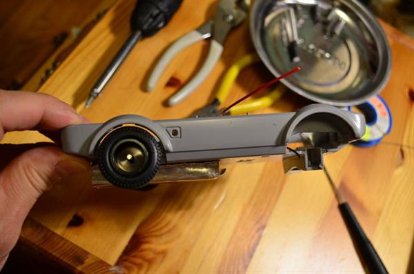
The first thing I had to do was modify some of the click-tabs which held the body to the chassis. I left the tab itself, but used a knife to shave off the small piece at the end which click-locked the tab into place. This allowed the two pieces to stay together, but without locking. It's a real pain to pull the two pieces apart if you don't do this. They actually stay together fairly well even without the lock pieces.
I also hot-glued the clear plastic of the headlights-piece and the red plastic of the taillights-piece into place. The pieces kept falling out as I played with the body of the cart and were in constant danger of loss or damage.
I also hot-glued the clear plastic of the headlights-piece and the red plastic of the taillights-piece into place. The pieces kept falling out as I played with the body of the cart and were in constant danger of loss or damage.
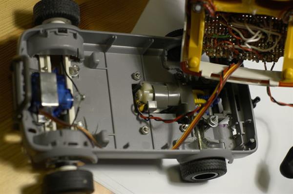
Step 3: The Motor and Gearbox
So, let's get started with the motor and gearbox. The most easily-available gearbox I could find was the Tamya "Single Gearbox (4-Speed)". It's really cheap (about $7) and easy to order over Amazon as well as many other places. It allows you to assemble the gearbox in 4 different ways, varying from slow-but-powerful to super-fast-but-weak. I originally used the slowest setting (the "A" option in the instructions), but eventually removed and rebuilt it in the next-faster configuration ("B"): the cart didn't need all that power, and at the slowest speed it wouldn't impress anyone. That change tripled the top speed, which was enough for this cart.
The biggest problem I faced with this gearbox was that the axle comes out of the middle of the gearbox. In order for the wheels to fit into the wheel wells in the Zoomobil easily, I needed a gearbox where the axle is at the bottom of the gearbox; this would allow me to secure the gearbox to the bottom of the chassis, and extend the axle out the sides. At the time I wasn't able to find a gearbox like this (although since then I've been made aware of one: Tamya Universal Gearbox Assembly. I can't actually say how well this would work, but it looks like it would).
In order to use the 4-speed Tamya gearbox, I considered a number of different configurations, including
set the gearbox above the back of the cart, with its wheels driving the the Zoomobil's wheels by friction,
set the gearbox with the motor "in the air" above the back of the mobile,
attach the gearbox to the underside of the chassis, making the cart look "jacked up",
as well as a number of others.
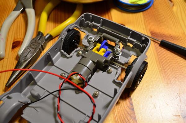
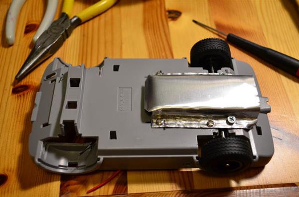
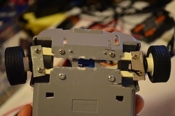
None of these configurations worked for me. In the end, it was clear that, in order to get the axle in the right place, I had to cut a gearbox-shaped hole in the bottom of the cart's chassis and set the gearbox into it. I cut the bottom of the chassis using my trusty Dremel cutter. I used sheet metal (to secure it from below) and narrow, long screws (from above) to "suspend" the gearbox in the correct place, so that the wheels fit into the wheel-well of the vehicle. The sheet metal below the gearbox had the added benefit of protecting the motor and gears.
I couldn't figure out any easy way to attach the original wheel hubs to the new axle. So, instead I used some hubs and wheels which were made for the Tamya gearbox. I didn't like that the hubs' rubber wheels didn't match the front wheels of the cart, though, so I popped them off and replaced them with the rubber from the original cart's wheels. The fit was a little sloppy at first, but never caused any problems. I thought also about painting the hubs white, to match the front (original) hubs, but never got around to it.
All this left about 1mm clearance under the cart. As long as the cart is only driven on hard surfaces, this isn't a problem.
One other very important point. In my prototype circuit, with my full-sized Arduino Uno and breadboard, whenever I got the motor up to a higher speed, the circuit would "freeze" in a particular state. In essence, it shut down or reset the Arduino. After some research on-line, I realized this was actually a rather well-known problem: motor noise. At higher speeds, the cheap motor's brushes were feeding so much electronic noise back into the circuit that it was shutting down the Arduino. The solution was to solder a set of very low-value capacitors across the motor terminals and housing. I followed these instructions at Beam-Wiki and my troubles went away. I needed to use the 3-capacitor solution.
The biggest problem I faced with this gearbox was that the axle comes out of the middle of the gearbox. In order for the wheels to fit into the wheel wells in the Zoomobil easily, I needed a gearbox where the axle is at the bottom of the gearbox; this would allow me to secure the gearbox to the bottom of the chassis, and extend the axle out the sides. At the time I wasn't able to find a gearbox like this (although since then I've been made aware of one: Tamya Universal Gearbox Assembly. I can't actually say how well this would work, but it looks like it would).
In order to use the 4-speed Tamya gearbox, I considered a number of different configurations, including
set the gearbox above the back of the cart, with its wheels driving the the Zoomobil's wheels by friction,
set the gearbox with the motor "in the air" above the back of the mobile,
attach the gearbox to the underside of the chassis, making the cart look "jacked up",
as well as a number of others.
None of these configurations worked for me. In the end, it was clear that, in order to get the axle in the right place, I had to cut a gearbox-shaped hole in the bottom of the cart's chassis and set the gearbox into it. I cut the bottom of the chassis using my trusty Dremel cutter. I used sheet metal (to secure it from below) and narrow, long screws (from above) to "suspend" the gearbox in the correct place, so that the wheels fit into the wheel-well of the vehicle. The sheet metal below the gearbox had the added benefit of protecting the motor and gears.
I couldn't figure out any easy way to attach the original wheel hubs to the new axle. So, instead I used some hubs and wheels which were made for the Tamya gearbox. I didn't like that the hubs' rubber wheels didn't match the front wheels of the cart, though, so I popped them off and replaced them with the rubber from the original cart's wheels. The fit was a little sloppy at first, but never caused any problems. I thought also about painting the hubs white, to match the front (original) hubs, but never got around to it.
All this left about 1mm clearance under the cart. As long as the cart is only driven on hard surfaces, this isn't a problem.
One other very important point. In my prototype circuit, with my full-sized Arduino Uno and breadboard, whenever I got the motor up to a higher speed, the circuit would "freeze" in a particular state. In essence, it shut down or reset the Arduino. After some research on-line, I realized this was actually a rather well-known problem: motor noise. At higher speeds, the cheap motor's brushes were feeding so much electronic noise back into the circuit that it was shutting down the Arduino. The solution was to solder a set of very low-value capacitors across the motor terminals and housing. I followed these instructions at Beam-Wiki and my troubles went away. I needed to use the 3-capacitor solution.
Step 4: The Steering
I used a simple, inexpensive servo in order to drive the steering: light, stable and reliable. The following problems surfaced immediately, though, just by looking at the cart:
how do I get the wheels to actually pivot?
how do I integrate the rotation of the servo's horn such that it causes that pivot?
how much modification do I need to do to the cart to get this to work?
Here's how I answered those questions.
how do I get the wheels to actually pivot?
how do I integrate the rotation of the servo's horn such that it causes that pivot?
how much modification do I need to do to the cart to get this to work?
Here's how I answered those questions.
Step 5: The Steering Linkage
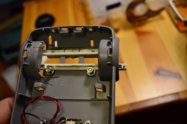

I did some research on-line, and eventually found the following simple linkage: two long, thin, parallel plastic struts, the front one fixed, and the back one free to slide left and right. Each wheel sits at the ends of these struts, on a flange (cut out of sheet-metal) which is screwed to the undersides of the ends of a strut-pair. When the back strut slides left, it kicks out the back side of the left wheel, and simultaneously pulls in the back side of the right wheel; and visa-versa sliding the other direction.
When I tried it, though, I eventually realized I simply had to depart from the original design of the cart. The wheels are rather wide, and pivoting them even the tiniest bit caused the wheels to rub against the inside of the wheel wells. So, as ugly as it was, I decided I had to move the wheels out from the wheel wells completely in order to get them to pivot sufficiently. I did this by using longer struts. I hated making this large of a change to the original appearance of the cart, but I had no choice.
After I had cut and assembled all this, I found out about Ackerman Steering Geometry, which uses L-shaped pieced in order to turn the wheels, effectively putting each front wheel at a slightly different turning radius while pivoted. It would have been a superior design, but I really didn't want to rebuild the front steering linkage. Besides, my cart doesn't really ever go fast enough for that to matter. If I were to do it over, though, I'd try to implement the Ackerman design.
Now the problem was to connect the servo to the steering linkage.
Step 6: Servo Control
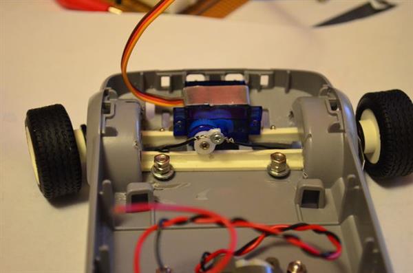
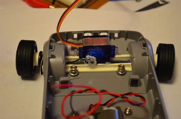
I secured the servo to the chassis using a band of sheet metal screwed down to the plastic. Again, I was struck by the fact that the design of the cart included enough space under the "hood" which allowed this without any external modifications.
The servo has a horn which rotates through a half circle. The Arduino can control the position of this horn with tremendous accuracy, speed and power. What I needed was to get the horn (or, just the servo's gear-head) to be able to move the back strut left and right. I came up with the following ideas:
make grooves in the strut which matched the grooves of the servo's head. I eventually decided against this as too difficult to get correct, and, truth be told, simply to much work.
point the horn downward, and put a notch in the strut that the servo's horn fit into. I decided against this, too, once I realized that the strut would move the most when the notch was directly under the servo, and less and less as it slid to the side. Eventually, the servo's horn would no longer be moving it left or right, but rather be trying to lift it off its track.
attach wires from the end of the horn to each end of the strut. The servo horn at the straight up (90 degrees) position would be centered, or "straight ahead". Then as the servo head moved to one side, it would pull one end of the movable strut with it. This was the option I finally decided on. Just like above, though, there's a point at which the rotational motion of the servo's horn changes from a left-right pull to a downward pull, at which point it was no longer useful. Luckily, though, I found out that my wheels actually got to their maximum pivot before the servo horn did this, so it was not an issue. Note that I had to cut the horn about in half to make it fit in this space.
Note that the mechanism I built really doesn't allow the cart to make sharp turns. It requires quite a turning radius.
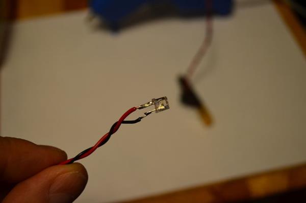
Step 7: The LEDs
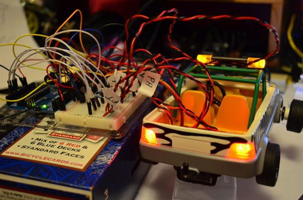
OK, so the chassis of the cart was cut up pretty extensively in order to accomodate the steering and motor gearbox, so the cart could move and be steered. Now it needed some flash...literally.
Like I wrote above: it just screamed to have real, working head, tail and flasher lights. I wanted two white headlights, two red taillights, and two yellow flashers on top (the flashers on top are soo cool!). I was started out using white LEDs for everything because everywhere I wanted color already had translucent, colored plastic. However, when I tried it, I found that the colored plastic wasn't nearly dark enough for bright LEDs: the light always looked simply white, regardless of the color of the translucent plastic. So I decided to actually use yellow LEDs for the flashers and red LEDs for the taillights. This achieved the effect I wanted beautifully.
The first thing I did was solder red/black pairs of wires to each LED and then label each at the circuit-board-end. The labels were necessary, and needed to be replaced a number of times, but were worth the effort. Also, I could have paired the LEDs to the same Arduino pin, but wiring each LED individually allowed me to program some interesting effects with them controlled by the remote.
Step 8: The Flashers
The flashers (the yellow lights mounted at the top of the green roll-cage) required the most work of all the LEDs. To achieve the desired effect, they had to fit within the "cup" of the yellow flasher housing, but they simply would not fit. In order for them to fit, I had to use a knife to shave off almost half of the LED's plastic lens. It turns out the lens consists of a hard outer shell with very soft plastic inside. After I pierced the shell, I actually had to be careful not to take off too much of the soft inner plastic. It just took a sharp knife and some whittling skills to modify the LED to the correct size. I also had to shave away some of the rim at the base of the LED on both sides (making two flat edges). I kept shaving away plastic until the LED fit into the yellow plastic flasher housing. But it did fit, without needing to change the housing itself.
Next, I had to cut away some of the underside of the black flasher base at the left and right edges so the LED wires would fit into the yellow flasher housing. I left the center plastic piece, though, for insulation between the LED wires. Finally, I ran the wires underneath the black flasher base. I used hot glue to keep the yellow housing, leds and wires in place (and, conveniently, insulated from each other). The rest of the wires ended up wrapped around the legs of the green roll-cage.
I hope I never need to replace those LEDs.
Step 9: The Headlights


I hot-glued the two white LEDs into some small reflectors I had cut from some old plastic parts. The reflector is not absolutely necessary, but I liked the effect. Then I hot-glued the LED and reflector into the front of the chassis so they shine through the clear headlight pieces. I used hot glue to secure the wires along the inside of the chassis to get it to the back of the cart, where the circuit board will be.
Step 10: The Taillights

For the taillights, I hot-glued the red LEDs to the back corners of the inside of the bed of the cart, just behind the clear plastic taillight pieces; no room for reflectors here. I brought the wires to just behind the seats and hot glued them to the inside of the bed of the chassis.
In all three cases, the design of the cart had left just enough space to fit the LED (and reflector) behind the clear plastic pieces. This, again, made me think it was designed to have lights. The flashers were a pain, but smaller LEDs would have made that easier.
In all three cases, the design of the cart had left just enough space to fit the LED (and reflector) behind the clear plastic pieces. This, again, made me think it was designed to have lights. The flashers were a pain, but smaller LEDs would have made that easier.
Step 11: The Passenger Compartment

I had to modify the yellow passenger compartment in a few ways. I had to cut a hole in the seat area, to leave room for the motor, otherwise it would not slide down onto place. I also removed the entire "truck bed" (the Zoomobil is basically a small pickup truck) in order to make space above the gearbox and below the circuit board.
I was sad to have to be forced to leave off the grey upper "truck bed". I really tried hard to keep that thing, mostly because without it you lose the attachment for the spare tire. But, it just wouldn't fit.
I was sad to have to be forced to leave off the grey upper "truck bed". I really tried hard to keep that thing, mostly because without it you lose the attachment for the spare tire. But, it just wouldn't fit.
Step 12: The IR Transmitter and Receiver
I learned that most IR transmitters (used for TVs, radios, etc.) work on a similar standard, which the cheap IR receiver I bought can "read". However, every manufacturer maps a different set of codes to the key-presses. Luckily the Adafruit site's tutorial for the IR receiver provides the code for a simple program which will output the values it receives when you press a key on a remote. After that, it was just a matter of capturing the values for the remote-button-presses for which I was interested, and inserting them into my program. Pretty simple stuff for an old programmer like myself. If you read the script_ (later) you'll see that I also started mapping the key values for another old remote we had sitting around.
Step 13: The Circuit Board (www.pcbway.com/e)


When it comes to the electronics side of things, I'm admittedly a novice. Consequently, I went through 3 different designs for the circuit board, including soldering down the headers and sockets. The first one I made so small that I wasn't able to solder the wires without making shorts. The second was the wrong shape to fit where I finally decided to put it. The last one wasn't perfect, either, but was good enough. This board is 6.5cm x 4cm. The soldering job on the underside of the board is, well, rather ugly. But, there aren't any shorts, and all the wires go where they are supposed to, so it works.
I designed the circuit board in a rather primitive way: I simply kept poking all the headers and sockets into the board until I found a good layout, meaning there was enough room for everything to fit, and to allow space for all the soldering I needed to do. Then I taped everything down and followed my circuit design to solder the wires on the underside. There are better ways to approach this (see next paragraph), but I didn't know that at the time. After I decided the best location for the board was in the back of the cart under the roll cage, that fixed the board's dimensions and also the positioning of a number of the components: all the power connectors had to be at the back, where the battery packs would be, and all the LED headers needed to be at the front, where I wanted their wires to emerge from underneath.
After I was done, a friend introduced me to a circuit-board layout designer program named Fritzing. If I had started with that, it would have saved me some time. I used that program to create the breadboard diagram above. I highly recommend that program.
People with sharp eyes will notice that all the LEDs are wired to the Analog pins (A0 through A5), EXCEPT one of the taillights. My original plan was to make the break lights "flash" bright for a second when the cart slowed down and then reset to a normal "low" setting. That would have been so cool! I needed two more PWM pins to do this, however, in order to vary the LCDs' brightness. I was already using pin 5 for the HBridge and pin 9 for the servo (and the servo library does something with pin 10, too, so it was useless for this). This left PWM pins 3, 6 and 11. I assumed 6 and 11 would work, so I soldered them up before fully testing them. It turns out, 6 worked fine, but 11 didn't, and likewise for pin 3: none of them were PWM anymore, simply digital outs. I didn't notice this problem until I had already soldered up the circuit board. After some testing and moving things around, I finally just left the taillights soldered to pins 6 and A5. My theory is that either the Servo or the IR library somehow interfered with the normal PWM mode on pins 3 and 11.
Step 14: The Batteries
During my research about batteries for such a beast as this, I found blogs and articles, all of which clearly advised people to avoid trying to use the same battery pack for the Arduino's power and the motor's power. Many of them were quite vehement about this.
Well, I didn't believe them. However, after trying to drive the Arduino, servo and motor all off of the same AA battery pack, I have to say that they were all totally and completely correct. After wiring this up, as soon as I started up the motor, it immediately reset the Arduino. The explanation is that the motor requires so much power that it causes a spike in the circuit, which makes the Arduino unhappy. OK, lesson learned: you simply MUST use two battery packs. There may be some electronics trick or component that could be used to solve this, but that's currently beyond me. Although not absolutely necessary (from my experimentation), I also decided to use the same battery pack for the servo as I did for the motor.
So now I have to make room in my Zoomobil for two battery packs: one for the electronics and one for the servo and motor. Try as I may, I was not able to fit all these batteries inside the Zoomobil chassis itself. I was hoping to put the batteries "under the hood", but there simply was too little space there, especially since the servo needed to have room to rotate. I also thought of putting it in the "truck bed", but I needed to put the circuit board there. The motor already hung underneath the chassis, so that was out. I suppose I could have put one or the other on top of the hood somehow, or even in the passenger seat, but that would have changed the appearance too much.
But, again, as if the Playmobil designers were anticipating someone needing space for a bunch of batteries, the Zoomobil actually comes complete with a trailer! I had not originally planned on including the trailer, but, in the end, I simply had to do so, in order to have a place for the two battery packs.
Something I did not explore at all was the use of LiPo rechargeable battery packs: the different geometry might have allowed them to fit in other places within the body. Something to think about for the future.
Step 15: The Script
The Arduino Uno script_ is attached below.
Well, I'm a C programmer from decades ago, so, for me, writing the software was a walk down memory lane, and was probably the easiest part of this entire project.
I decided to abstract out the actual low-level drivers for the motor, IR, servo and LEDs. Although I was too lazy to actually go the full object-oriented route and separate these features into their own C++ classes, it wouldn't be hard to do so. That exercise is left for the reader.
Steering
I partitioned the wheel positions into a discreet number of steps left and right, so that pressing the left- or right-arrow buttons on the remote adds to or subtracts from the current turn-value (with range checks). This was then mapped to a percentage value (-100% thru 100%, where 0 means "straight-ahead"), which leaves it to the lowest level to decide how many actual degrees represent 100%, and feed that value to the servo. This gave me the most flexibility in the code to tweek the max left/right turn degrees, as well as how many button presses it takes to get there. I also used the center button (between the left- and right-arrows) to center the wheels immediately (set turn-value to 0).
Speed
I did something similar with the motor speed forward and backward: I created a discreet range of steps for the speed, ranging from a positive number, through 0, to a negative number: positive is forward, 0 is stop, negative is backward. As you press the up-arrow, it increases the current value; as you press the down-arrow, it decreases it (with range checks). There's also one button which sets the speed to 0 (stop). The high level code maps that number to a percentage value (-100%..100%) and then passes it down to the low level code, which maps that to the Arduino's range (namely, 0-255) to drive the HBridge. Again, all this abstraction allowed me to tweek the speed range, forward and backward, as well as the number of button-presses it takes to get to 100%.
In the future, I might employ something more like a joystick to control these functions, though, since IR remote's keypad is rather clumsy to use.
LEDs
Programming the lights was probably the most fun. I set up a generic state-machine driver and then defined separate sets of state machines for each pair of LEDs. This allowed me to drive each of the 6 LEDs with pre-defined patterns either together or independently.
I arbitrarily mapped the number pad buttons to be used as LED controls: 4 means left-turn signal, 6 right-turn, 5 warning flashers, and others as necessary. It would have been nice for the left- and right-turn buttons to be toggles, but I never got to that in the program.
Step 16: Conclusion
So, that was it.
I had a lot of fun putting this together, solving problems, poking wires into bread-boards, learning about servos, motors and electronics. I hope you learned something from this Instructable, or that it inspired you to try something like this yourself.
[Welcome to visit www.pcbway.com/e to know more about PCBs.]
website: www.pcbway.com/e
For PCB prototype, please feel easy contact Erin KOU (erin.kou@pcbway.com)
没有评论:
发表评论